
Introduction
This book is a collection of guided projects and knowledge to help you get started with embedded Rust.
How to use this Book
The book consists of several sections:
- Instructions for the knurling-sessions projects
- Reference Material
- Knowledge
- Troubleshooting Pages
To build one of the quarterly knurling-sessions projects and to collect as much embedded knowledge as possible on the way, work through the instructions of each project in order. The Reference Material section contains more general instructions to help you get started with a project from scratch. Some of the instructions from knurling-sessions projects depend on this part. When ever this is the case, we link to the appropriate section. The Knowledge section contains a glossary and articles about embedded concepts to help you dig deeper into the subject. The Troubleshooting pages contain help for common problems when setting up projects.
Icons and Formatting we use
We use Icons to mark different kinds of information in the book:
- ✅ Call for action
- ❗️ Warnings, Details that require special attention
- 🔎 Knowledge, that gets you deeper into the subject, but you do not have to understand it completely to proceed.
- 💬 Descriptions for Accessibility
Note: Notes like this one contain helpful information
Course Material
Knurling-sessions aims to be as inclusive as possible. This means that some information is available in several forms, for example pictures and text description. We also use icons so that different kinds of information are visually distinguishable on the first glance. If you have accessibility needs that are not covered, please let us know.
Knurling Sessions 2020 Q4: Building a CO2 Sensor
In the first Knurling-sessions project, we will be incrementally building a CO2 sensor. This is not only a fun way to explore working with electronics and embedded Rust, in the end you'll also have a useful helper, especially if you're working from home: CO2 levels have a significant impact on your ability to concentrate and make decisions, and they drop faster than you think! The device we're building will tell you when it's time to open a window.
The first month is about learning some basics of embedded development and Rust. The SCD30 Sensor will be implemented in the second month. The third month is about embedded graphics and display.
Example code
The example code and the source of this book can be found at https://github.com/knurling-rs/knurling-session-20q4.
Contribute
If something is unclear or you have a suggestion for the book please open an issue, or send a PR!
Preparations
This chapter contains informations about knurling-sessions, the standard hardware and an installation guide.
Standard Hardware
Knurling Sessions 2020 Q4 assumes you're using the nRF52840 Development Kit (DK) as your development board. You can also use any other board supported by probe-run, but you may have to make some modifications to the provided instructions on your own.
The DK needs to be connected to your PC with 1 micro-USB cables (make sure they're data cables and not just for charging). The chapter on checking your hardware will provide you with more details.
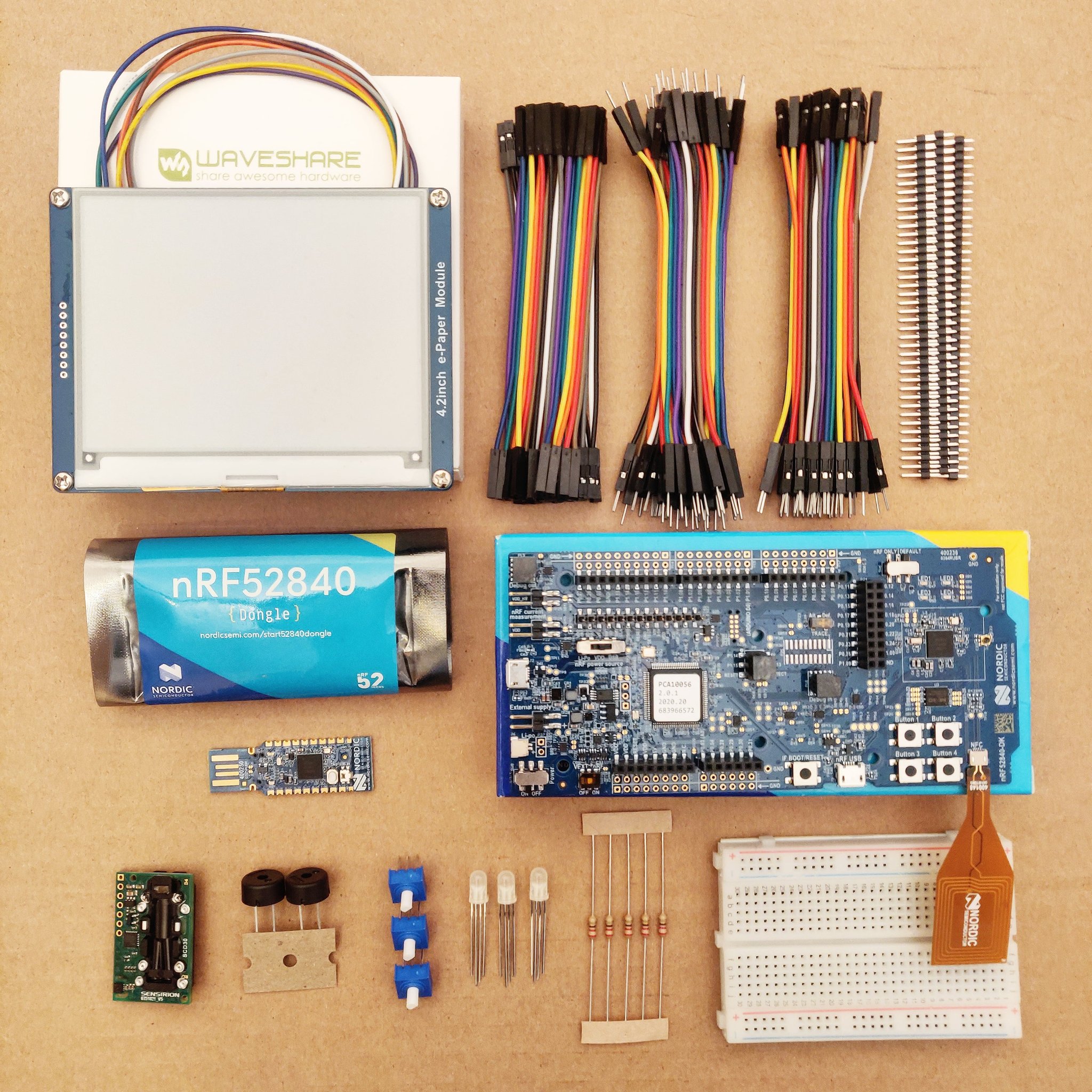
You'll need a few more peripherals and parts - all in all:
Bill of Materials
Block 1: Getting started with embedded Rust

- 1x nrf52840-DK (or other nrf52XXX boards)
- 1x RGB-LED (or single colored LED(s) and/or on-board LEDs)
- 3x 220 Ohm Resistors
- 1x Potentiometer
- 1x Breadboard
- 1x Jumper wires (40 wires) - Pin to Pin
- 1x Jumper wires (40 wires) - Pin to Receptacle
- 1x Jumper wires (40 wires) - Receptacle to Receptacle
Block 2: Adding the CO2 Sensor

Note: Soldering is required for this step to connect the headers of the Sensirion gas sensor. Alternatively, you may be able to use "Hook Probes", such as the ones offered by Adafruit, instead of soldering. These are also often available in bulk from websites such as Aliexpress.
- 1x Sensirion SCD30 CO2 Sensor (or other air quality sensor)
- 1x Pin Headers (40 piece)
- 1x Piezo buzzer
Block 3: Embedded Graphics

Note: Soldering is required for this step to connect the headers of the Waveshare display. Alternatively, you may be able to use "Hook Probes", such as the ones offered by Adafruit, instead of soldering. These are also often available in bulk from websites such as Aliexpress.
- 1x Waveshare 4.2 inch b&w ePaper Display
Checking the Hardware
nRF52840 Development Kit (DK)
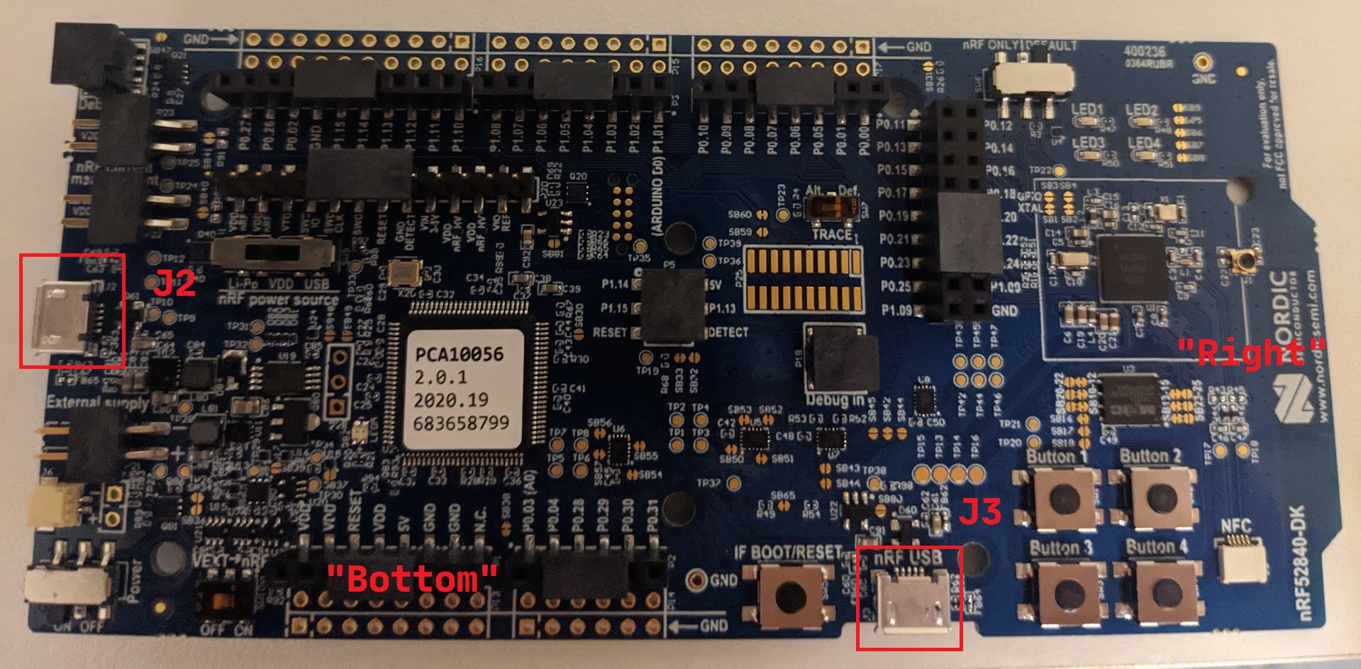
Connect one end of a micro USB cable to the USB connector J2 of the board and the other end to your PC.
💬 These directions assume you are holding the board "horizontally" with components (switches, buttons and pins) facing up. In this position, rotate the board, so that its convex shaped short side faces right. You'll find one USB connector (J2) on the left edge, another USB connector (J3) on the bottom edge and 4 buttons on the bottom right corner.
After connecting the DK to your PC/laptop it will show up as:
Windows: a removable USB flash drive (named JLINK) and also as a USB Serial Device (COM port) in the Device Manager under the Ports section
Linux: a USB device under lsusb. The device will have a VID of 0x1366 and a PID of 0x1015 -- the 0x prefix will be omitted in the output of lsusb:
$ lsusb
(..)
Bus 001 Device 014: ID 1366:1015 SEGGER 4-Port USB 2.0 Hub
The device will also show up in the /dev directory as a ttyACM device:
$ ls /dev/ttyACM*
/dev/ttyACM0
macOS: a removable USB flash drive (named JLINK) in Finder and also a USB device named "J-Link" when executing ioreg -p IOUSB -b -n "J-Link".
$ ioreg -p IOUSB -b -n "J-Link"
(...)
  | +-o J-Link@14300000  <class AppleUSBDevice, id 0x10000606a, registered, matched, active, busy 0 $
  |     {
  |       (...)
  |       "idProduct" = 4117
  |       (...)
  |       "USB Product Name" = "J-Link"
  |       (...)
  |       "USB Vendor Name" = "SEGGER"
  |       "idVendor" = 4966
  |       (...)
  |       "USB Serial Number" = "000683420803"
  |       (...)
  |     }
  |
The device will also show up in the /dev directory as tty.usbmodem<USB Serial Number>:
$ ls /dev/tty.usbmodem*
/dev/tty.usbmodem0006834208031
The board has several switches to configure its behavior. The out of the box configuration is the one we want. If the above instructions didn't work for you, position the board so that the Button descriptions are horizontal and check the position of the on-board switches:
- Switch SW6, on the top edge right corner, is set to the DEFAULT position; this is the right position of the two possible positions (nRF = DEFAULT).
- Switch SW7, which is slightly up and to the right of the center of the board, is set to the Def. position; this is the right position of the two possible positions (TRACE = Def.). Note that this switch is protected by Kapton tape.
- Switch SW8, on the bottom edge left corner, is set to the ON position; this is the left position of the two possible positions (Power = ON)
- Switch SW9, to the right the left edge USB connector (J2), is set to the VDD position; this is the center position of the three possible positions (nRF power source = VDD)
- Switch SW10, on the bottom edge left corner and to the right of the SW8 switch, is set to the OFF position; this is the left position of the two possible positions (VEXT -> nRF = OFF). Note that this switch is protected by Kapton tape.
Installation Instructions
Rust and tooling
Base Rust installation
Go to https://rustup.rs and follow the instructions.
Windows: Do install the optional components of the C++ build tools package. The installation size may take up to 2 GB of disk space.
probe-run
probe-run is a custom Cargo runner that lets you run embedded apps as if they were native apps. Install version v0.1.4 or newer:
$ cargo install probe-run
cargo-generate
cargo-generate generates a new Rust project from a predefined template of choice for you. Install it like so:
$ cargo install cargo-generate
flip-link
install flip-link
cargo install flip-link
Rust Analyzer
If you use Visual Studio Code, we recommend you install Rust Analyzer to help you during development.
Windows: It's OK to ignore the message about git not being installed, if you get one!
OS specific dependencies
Linux only: Access USB Devices as non-root User
Some of our tools depend on pkg-config and libudev.pc. Ensure you have the proper packages installed; on Debian based distributions you can use:
$ sudo apt-get install libudev-dev libusb-1.0-0-dev
To access the USB devices as a non-root user, follow these steps:
- Create the following file with the displayed contents. You'll need root permissions to create the file.
$ cat /etc/udev/rules.d/50-knurling.rules
# udev rules to allow access to USB devices as a non-root user

# nRF52840 Development Kit
ATTRS{idVendor}=="1366", ATTRS{idProduct}=="1015", TAG+="uaccess"
- Run the following command to make the new udev rules effective
$ sudo udevadm control --reload-rules
Windows only: Zadig JLink driver
On Windows you'll need to associate the nRF52840 Development Kit's USB device to the WinUSB driver.
To do that connect the nRF52840 DK to your PC using micro-USB port J2 (as done before) then download and run the Zadig tool.
In Zadig's graphical user interface,
-
Select the 'List all devices' option from the Options menu at the top.
-
From the device (top) drop down menu select "BULK interface (Interface 2)"
-
Once that device is selected,
1366 1015should be displayed in the USB ID field. That's the Vendor ID - Product ID pair. -
Select 'WinUSB' as the target driver (right side)
-
Click "Install WinUSB driver". The process may take a few minutes to complete.
CO2 Sensor Project
Now that we've checked our hardware, let's get started on building our CO2 sensor!
Block 1: Basics with Hardware
Hello World
This is a step by step guide expand the hello.rs example in the knurling app template from just logging hello world to blinking an onboard LED on the nrf52840-DK.
An example of this implementation can be found here: 1_hello_extended.rs.
Project Setup
Come up with a name for the Project and generate the app template according to our guide. Don't forget to enter the appropriate Information in the TODOs.
Getting Access to Resources
- In your generated app-template folder, go to
src/bin/hello.rs. - Bring the following modules into scope:
#![allow(unused)]
fn main() {
use nrf52840_hal::{
    self as hal,
    gpio::{p0::Parts as P0Parts, Level},
    Timer,
};
}
The nrf52840_hal crate is a Hardware Abstraction Layer (HAL), which helps us access the board's resources, e.g. GPIO pins or timers.
If you use a different microcontroller, you need to be able to gain access to a TIMER peripheral, pins for the onboard LEDs and Level of the pins.
- Gain access to all the peripherals of the board by adding the following line in
fn main():
#![allow(unused)]
fn main() {
let board = hal::pac::Peripherals::take().unwrap();
}
If you use a different board, check the crate's docs on how to get access to all peripherals.
- You need a timer to blink LEDs, as the LED is on and off for certain amounts of time. To access the timer peripheral add this line:
#![allow(unused)]
fn main() {
let mut timer = Timer::new(board.TIMER0);
}
- If we want to use the onboard LEDs, we need to find out how to access them. Check the datasheet of your board to find out which GPIO pins they are connected to. For the nrf52840-DK you'll find the information here.
The onboard LEDs are part of the P0 Pins. LED1 is p0.13. To gain access this group of pins add this line:
#![allow(unused)]
fn main() {
let pins = P0Parts::new(board.P0);
}
Switching the Light on
- Configure pin p0.13 into a push-pull-output with Low Level:
#![allow(unused)]
fn main() {
let mut led_1 = pins.p0_13.into_push_pull_output(Level::Low);
}
- The
embedded-halcrate provides a generic API to access the different resources of a board, independent of board model. This makes development easier and your code more portable. We want to use it to set a pin high or low, or set delays for the Timer.
To access it, add it as a dependency to your Cargo.toml
 # Cargo.toml
 [dependencies]
 cortex-m = "0.6.3"
 cortex-m-rt = "0.6.12"
 # TODO(4) enter your HAL here
 nrf52840-hal = "0.11.0"
+embedded-hal = "0.2.4"

 [features]
and then, in hello.rs, bring its DelayMs and OutputPin Traits into scope so we can use them:
#![allow(unused)]
fn main() {
use embedded_hal::{
    blocking::delay::DelayMs,
    digital::v2::OutputPin,
};
}
- Add a delay of 1000 milliseconds to your
main()function:
#![allow(unused)]
fn main() {
timer.delay_ms(1000u32);
}
- Run the program!
LED1 on your microcontroller should light up for a second. Then the program ends.
Blinking the LED
- Open a loop:
#![allow(unused)]
fn main() {
loop {

};
}
- Inside the loop add the following lines:
#![allow(unused)]
fn main() {
    led_1.set_high().unwrap();
    timer.delay_ms(1000u32);
    led_1.set_low().unwrap();
    timer.delay_ms(1000u32);
}
- Run the program.
LED1 should blink continuously.
External RGB LED
Required Components
- 1 RGB LED
- 3 220 Ohm Resistors
- Breadboard
- Jumper cables
❗️❗️❗️ There are common anode and common cathode RGB LEDs. If you just took one from your stash, compare what the bulb of the LED looks like in relation to where the longest leg is:
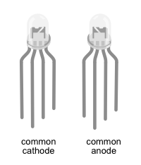
The LED in our shopping list is a common anode RGB LED. For now we'll provide instructions for both types.
Wiring
❗️❗️❗️ Before you start to wire things up, make sure, your breadboard and the nRF52840-DK is disconnected from any power source.
Common Anode RGB LED
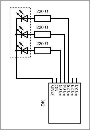
We have provided two ways that depict the wiring of this setup:
A circuit diagram which is focused on showing what parts are connected in what ways. This type of diagram neglects physical appearance of the parts and how the parts arranged in the physical world.
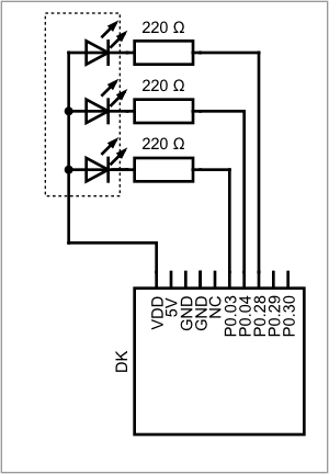
The breadboard diagram focuses on appearance of the parts and how they are arranged on a breadboard, while still showing the correct wiring.

✅ Compare both diagrams for how they depict the RGB LED.
✅ Wire the parts according to the breadboard diagram. The longest leg of the LED is connected to VDD. The single leg on one side is the red channel, on the other side are the channels for blue and green.
✅ Double check your wiring before connecting the board to the computer.
Common Cathode RGB LED
We have provided two ways that depict the wiring of this setup:
A circuit diagram which is focused on showing what parts are connected in what ways. This type of diagram neglects physical appearance of the parts and how the parts arranged in the physical world.
The breadboard diagram focuses on appearance of the parts and how they are arranged on a breadboard, while still showing the correct wiring.

✅ Compare both diagrams for how they depict the RGB LED.
✅ Wire the parts according to the breadboard diagram. The longest leg of the LED is connected to ground. The single leg on one side is the red channel, on the other side are the channels for green and blue.
✅ Double check your wiring before connecting the board to the computer.
Code
An example of this implementation can be found here: 2_hello_external_led.rs.
You can either work on the same file from the hello world example, or work on a copy of it. We assume, that you have access to the p0 pins. In the first example, we configured one pin. That one pin was special in the sense, that it only gives access to one of the onboard LED's. Now we need three GPIO pins, one for red, one for blue one for green.
✅ Configure three gpio pins, P0.03, P0.04 and P0.28 into push-pull-output pins, the initial level is High for common anode, and Low for common cathode.
✅ Add a 1000ms delay.
✅ Try running your code. If something lights up, you wrote code for the other type of LED.
Using the methods .set_high().unwrap(); or .set_low().unwrap(); on each of the pins will change the status of your LED.
✅ Try out all possible combinations of switching the channels on or off. What colors can you make?
✅ Build a blinking loop, where the LED blinks between two colors of your choice.
Internal Temperature Sensor
An example of this implementation can be found here: 3_temperature.rs.
✅ Preparations: have the board and the timer peripheral initialized in your code.
Before we start to work with an external sensor, where we would have to write a driver, we will access the board's internal temperature sensor first. We'll take a look at the HAL to learn more about how accessing peripherals works in detail and how methods work in Rust.
✅ Open the nrf-hal-common 0.11.1
✅ Open /src/temp.rs, the place where the communication with the boards temperature sensor is implemented.
The integrated temperature is a struct: pub struct Temp(TEMP). It needs to be public, so it can be called from the outside. TEMP is a type defined in the peripheral access crate (pac), it accesses the temperature sensor's register block. In the impl block are all the methods that are defined for Temp.
Methods are different from functions in that they are attached to objects. Let's look at them in detail:
pub fn new() takes TEMP as argument and returns Temp. The method takes ownership of the temperature sensor's register block.
✅ In order to be able to use Temp in your code, you have to bring it into scope first. Add the following lines to your code:
#![allow(unused)]
fn main() {
use nrf52840_hal::{
    self as hal,
    Temp,
    Timer,
};
}
✅ Take ownership of the temperature sensor's register block by calling the new method, using board.TEMP as argument. The variable needs to be mutable.
#![allow(unused)]
fn main() {
let mut temp = Temp::new(board.TEMP);
}
Now that we have an instance of the temperature sensor, we can take a measurement.
✅ Go back to temp.rs in the HAL code.
fn measure() takes a mutable reference to self as an argument. self is the instance of the temperature sensor that was created with fn new(). The method will stop a measurement, if one has already been started, starts a new measurement and block the program until it has completed the measurement and then returns a fixed point number I30F2. The second option is starting a measurement with fn start_measurement() and reading the measurement with fn read() which works in a non-blocking way. A measurement is started or stopped by writing to the register.
We'll stick with the blocking method fn measure() for now.
✅ In your code, add a line that takes a measurement, and one that logs the temperature value.
#![allow(unused)]
fn main() {
let temperature = temp.measure();
defmt::info!("{:?}", temperature);
}
The syntax reflects that methods are attached to objects: The argument &mut self refers to the object in front of the dot, and the parenthesis remain empty.
If you run the code now, you'll run into a compiler error, because the trait defmt::Format is not implemented for I30F2, the return type of fn measure().
✅ Add another method to_num() behind fn measure(). This method casts the fix point number into an f32. In order to be displayable, the type needs to be indicated in the format string.
#![allow(unused)]
fn main() {
let temperature: f32 = temp.measure().to_num();
defmt::info!("{=f32} °C", temperature);
}
✅ Initialize a loop that measures and displays the temperature every 60 seconds.
More about Methods
In this section, you will write your own methods.
An example of this implementation can be found here: 4_external_led_methods.rs.
We assume you used a common anode RGB LED. If you use a common cathode RGB LED, the settings high and low are the other way round.
✅ Go back to your code for the external RGB LED.
Instead of setting the Level for each of the channels individually, we can define a type that contains all three channels and methods that define the behavior of the RGB LED.
✅ Bring the GPIOS as well as the pin configurations into scope.
#![allow(unused)]
fn main() {
use nrf52840_hal::{
    self as hal,
    gpio::{
        p0::{Parts as P0Parts, P0_03, P0_04, P0_28},
        Level, Output, PushPull,
    },
    Timer,
};
}
✅ Above fn main(), define a struct with three fields, one for each channel. Each channel has it's own type!
#![allow(unused)]
fn main() {
struct LEDState {
    r: P0_03<Output<PushPull>>,
    b: P0_04<Output<PushPull>>,
    g: P0_28<Output<PushPull>>,
}
}
✅ Under the struct LEDState, create an impl block for that struct.
#![allow(unused)]
fn main() {
impl LEDState {
    // empty
}
}
There are two types of methods: static methods and instance methods. Static methods are generally used as constructors of an instance. They are called with the :: syntax. Instance methods are called by an object, this is why they have a reference to that object as argument. They are called with the dot syntax.
✅ Inside the impl block create a static method that constructs the struct. The first part of the methods configures the pins, the second part creates the struct, which is then returned.
#![allow(unused)]
fn main() {
fn init(pins: P0Parts) -> LEDState {
    let mut led_red = pins.p0_03.into_push_pull_output(Level::High);
    let mut led_blue = pins.p0_04.into_push_pull_output(Level::High);
    let mut led_green = pins.p0_28.into_push_pull_output(Level::High);

    LEDState {
        r: led_red,
        b: led_blue,
        g: led_green,
    }
}
}
✅ Inside fn main() substitute the 3 lines that configure the pins with calling this static method.
- let mut led_red = pins.p0_03.into_push_pull_output(Level::High);
- let mut led_blue = pins.p0_04.into_push_pull_output(Level::High);
- let mut led_green = pins.p0_28.into_push_pull_output(Level::High);

+ let mut light = LEDState::init(pins);
We can now define all sorts of instance methods that control the behavior of the LED. As an example we will refactor this piece of code that switches the led from red light to blue light with a 1000ms interval:
#![allow(unused)]
fn main() {
loop {
    led_red.set_low().unwrap();
    led_blue.set_high().unwrap();

    timer.delay_ms(1000_u32);

    led_red.set_high().unwrap();
    led_blue.set_low().unwrap();

    timer.delay_ms(1000_u32);
    }
}
✅ Go back to the impl block. Define an instance method that sets the red channel low and the others high.
#![allow(unused)]
fn main() {
fn red(&mut self) {
    self.r.set_low().unwrap();
    self.g.set_high().unwrap();
    self.b.set_high().unwrap();
}
}
The methods takes a mutable reference of the instance of LEDState as argument. &mut self is short for self: &mut Self. The fields of the struct can be accessed with the . syntax.
✅ Define a method that sets the blue channel high and the others low in the same way.
✅ Go back to fn main() inside the loop substitute the lines with the corresponding function call.
- led_red.set_low().unwrap();
- led_blue.set_high().unwrap();
+ light.red();

  timer.delay_ms(1000_u32);

- led_red.set_high().unwrap();
- led_blue.set_low().unwrap();
+ light.blue();

  timer.delay_ms(1000_u32);
✅ Turn this blinking loop into a method that can be called.
Right now, the pins for the LED are hard coded. This makes the code hard to reuse for a second LED. Let's refactor this part of the code.
✅ Bring the Pin type and the prelude::* module into scope.
#![allow(unused)]
fn main() {
use nrf52840_hal::{
    prelude::*,
    gpio::{
        Level,
        Output,
        PushPull,
        Pin,
    },
    Timer,
};
}
✅ In the struct definition, substitute the specific pins with the Pin type.
#![allow(unused)]
fn main() {
struct LEDColor {
    r: Pin<Output<PushPull>>,
    b: Pin<Output<PushPull>>,
    g: Pin<Output<PushPull>>,
}
}
✅ Modify the init method, so the pins it will take can be any numbered pin, but they can also be in any configuration. The method will, when instantiating the LEDColor struct, configure the pins into a push-pull output, with high level.
Note the generic type parameter <Mode>. It needs to be declared right after the function name, so that it can be used in the type declaration of the arguments. <Mode> is a place holder for the unknown pin configuration.
#![allow(unused)]
fn main() {
pub fn init<Mode>(led_red: Pin<Mode>, led_blue: Pin<Mode>, led_green: Pin<Mode>) -> LEDColor {

    LEDColor {
        r: led_red.into_push_pull_output(Level::High),
        b: led_blue.into_push_pull_output(Level::High),
        g: led_green.into_push_pull_output(Level::High),
    }
}
}
✅ Rewrite the lines in fn main() so that the code works.
#![allow(unused)]
fn main() {
let led_channel_red = pins.p0_03.degrade();
let led_channel_blue = pins.p0_04.degrade();
let led_channel_green = pins.p0_28.degrade();

let mut light = LEDColor::init(led_channel_red, led_channel_blue, led_channel_green);
}
Adding User - Input
This section focuses on getting the buttons to work, so you can interact with the hardware!
An example of this implementation can be found here: 5_led_with_buttons.rs.
The buttons on the board are numbered pins, just like the on-board LED's. Their pins are p0.11, p0.12, p0.24 and p0.25.
✅ Bring the gpio module with p0 parts into scope and add a line to fn main() that gives you access to the p0 pins.
✅ Build a type and a static method for the buttons. This static method will take pins of any configuration and turn them into a pull-up input.
#![allow(unused)]
fn main() {
pub struct Button(Pin<Input<PullUp>>);

impl Button {
    fn new<Mode>(pin: Pin<Mode>) -> Self {
        Button(pin.into_pullup_input())
    }
}
}
✅ Create an instance of a button:
#![allow(unused)]
fn main() {
let button_1 = Button::new(pins.p0_11.degrade());
}
In order to have an effect, we first need to know the status of the button. Is the button pushed or not? Next, we have to connect an event with the button state.
✅ Inside the impl Button block, implement an instance method that returns true if the button is pressed:
#![allow(unused)]
fn main() {
pub fn is_pressed(&self) -> bool {
    self.0.is_low().unwrap()
}
}
Note, that struct Button does not have any named fields. To access the associated type, index with 0.
✅ Inside fn main(), implement one of the onboard LEDs.
✅ Continue to write the program, so that the LED is on, when the button is pushed and off, when the button is not pushed.
Adding User Input - Advanced
Convert Temperature Unit by pushing a Button
The user experience is pretty straight forward: the program does one thing while the button is pressed, and another thing when the button is not pressed. This gets more complicated when pressing a button should only trigger a one-time event like switching the way temperature is displayed.
An example of this implementation can be found here: 8_temp_unit_convert_buttons.rs.
✅ Start with the file from the last chapter.
✅ Bring the following resources into scope:
#![allow(unused)]
fn main() {
use nrf52840_hal::{
    self as hal,
    gpio::{p0::Parts as P0Parts, Input, Pin, PullUp},
    prelude::*,
    Temp,
    Timer,
};
}
We want to be able to switch the unit in which the temperature is displayed, while the temperature is updated regularly. Since some of the programs behavior depends on the current choice of unit, that unit needs to be kept track of.
There are three common ways of displaying Temperature: Celsius, Kelvin and Fahrenheit. They are three variants of the same concept, this calls for the use of an enum for this type.
✅ Add the following enum before the struct Button.
#![allow(unused)]
fn main() {
enum Unit {
    Fahrenheit,
    Celsius,
    Kelvin,
}
}
The sensor gives out the temperature in degrees Celsius.
✅ Go to fn main(). Before the loop, add a variable that sets the current display unit.
#![allow(unused)]
fn main() {
let mut current_unit = Unit::Celsius;

loop {
    // ...
}

}
We can define methods for an enum in the same way we can do that for a struct.
✅ Add a method to the enum Unit, that contains a match statement. In each of the match arms, implement the conversion of the temperature value to the corresponding unit.
#![allow(unused)]
fn main() {
impl Unit {
    fn convert_temperature(&self, temperature: f32) -> f32 {
        match self {
            Unit::Fahrenheit => {
                // convert and return temperature
            },

            Unit::Kelvin => {
                // convert and return temperature
            },

            Unit::Celsius => {
                // return temperature as it is
            },
        };
    }
}
}
Now we need to implement the change of the unit on pressing a button.
✅ Go to fn main(). Inside the loop, use a match statement that, depending on the current unit, switches to different one if the button is pressed. Add a log statement, that indicates, that the unit was changed.
#![allow(unused)]
fn main() {
if button_1.is_pressed() {
    current_unit = match current_unit {
        Unit::Fahrenheit => Unit::Kelvin,
        Unit::Kelvin => Unit::Celsius,
        Unit::Celsius => Unit::Fahrenheit,
    };
    defmt::info!("Unit changed");
};
}
✅ Run the program. Upon pressing the button, you should see continuous log output.
✅ Implement a periodic timer instance. Use this timer instead of the regular one.
#![allow(unused)]
fn main() {
let mut periodic_timer= Timer::periodic(board.TIMER0);
}
✅ Inside the loop, after the temperature is read from the sensor, call the convert_temperature method on the current_unit and bind to a new variable. This is followed by a match statement, that prints the temperature value with the right unit displayed to the log.
#![allow(unused)]
fn main() {
loop {
    let temperature: f32 = temp.measure().to_num();
    let converted_temp = current_unit.convert_temperature(temperature);

    match current_unit {
        Unit::Fahrenheit => defmt::info!("{=f32} °F", converted_temp),
        Unit::Kelvin => defmt::info!("{=f32} K", converted_temp),
        Unit::Celsius => defmt::info!("{=f32} °C", converted_temp),
    };
    if button_1.is_pressed() {
        // ...
    };
}
}
✅ Run the program.
This should lead to many log outputs displaying the temperature in the current unit. Pushing the button once, changes the unit a number of times, so changing it intentionally to a certain unit is impossible.
✅ Add a delay of 100 ms to the end of the loop.
#![allow(unused)]
fn main() {
loop {
    // ...

    if button_1.is_pressed() {
        // ...
    };
    periodic_timer.delay_ms(100_u32);
}
}
✅ Run the program.
While the program kind of does what we want, the user experience is quite horrible. Let's improve that.
An example of this implementation to this point can be found here: 7_temp_convert_button_noisy.rs.
A first step is to define the behavior we want to see a bit more detailed. Let's look at three components.
State of the button out of human perspective
A button can be in four states:
- It can be pressed
- It can be not pressed
- It can be in transition from pressed to not pressed
- It can be in transition from not pressed to pressed
To define these states a bit more binary, we can look at these states by asking in what position the button was last, and in what position it is now.
| was | is | |
|---|---|---|
| 1. | pressed | pressed |
| 2. | not pressed | not pressed |
| 3. | pressed | not pressed |
| 4. | not pressed | pressed |
State of the button out of machine perspective
While the human perspective seems pretty straight forward, determining what the button states mean in hardware is a bit more complicated. In theory pushing a button causes a signal change, but this change is often not so clean and rather noisy, especially when the button gets older. Compensating for this behavior is called debouncing a button. In software, this can be done by having a state machine that keeps track of the 4 states of the button, and by defining that a pushed button counts as a pushed button if it is pushed for a certain amount of time and not because of a sudden signal spike, because a conductive dust spec got in the way.
Persistence of system change
We implement buttons, because we want people to be able to interact with a system and change the systems behavior by pushing a button. This change can either be only there while the button is pressed and ended by it's release, or started by pressing a button and persisting despite the button is released.
What should the program behavior be like?
We want to change the unit in which the temperature is displayed by pressing a button. The change should persist once the button is released. We use one of the button's transition from "being pressed" to "not being pressed" as the triggering event for the unit conversion. To detect the button's transitions, the program keeps track of the past state of the button. The temperature should be displayed every 1000ms.
Improve Button behavior
✅ Add another field to the button struct, that keeps track of the button's past state with a bool. The initial state is false.
Note that the former anonymous struct now has fields. This change needs to be reflected in the methods that are implemented for this struct.
#![allow(unused)]
fn main() {
struct Button {
    pin: Pin<Input<PullUp>>,
    was_pressed: bool,
}
}
✅ Add a method to the impl Button block that detects a rising edge in the signal by
- reading the current state of the button
- comparing the current state with the past state, which is saved in the button struct.
- returns
true, if button was pressed, but currently is not pressed. - updating the past state of the button.
#![allow(unused)]
fn main() {
fn check_rising_edge(&mut self) -> bool {

    let mut rising_edge = false;

    let is_pressed = self.is_pressed();
    // Only trigger on "rising edge" of the signal
    // Term: "Edge Triggering"
    if self.was_pressed && !is_pressed {
        // Was pressed, now isn't:
        rising_edge = true;
    }
    self.was_pressed = is_pressed;
    rising_edge
}
}
✅ Go to fn main(). Declare the button's pin as mutable. Substitute the is_pressed method with check_rising_edge().
#![allow(unused)]
fn main() {
let mut button_1 = Button::new(pins.p0_11.degrade());

loop {
    // ...
    if button_1.check_rising_edge() {
        // ...
    }
    // ...
}
}
✅ Run the program.
No matter how long you push the button, the unit only changes once. If you don't push the button more than once within 100 ms, every interaction is registered. But our log output is still 10 times more than planned and button timing is not ideal.
Timing
In order to detect all human button interactions and register the button's state, the button state needs to be read quite often. To filter out noise from the hardware, reading the button about every 5 ms is enough. We're looking to detect a rising edge, that is long enough to be intentional. Reacting on the rising edge of the button release, after a falling edge of a button press gives even more assurance, that the signal is intentional.
On a high level the implementation looks like this: A timer counts up until 1000 microseconds. Every time 1000 µs have passed, a counter that keeps track of passed milliseconds is updated. If the number of passed milliseconds is divisible by 5 and a rising edge is detected, the unit is changed. Every time the number of passed milliseconds is divisible by 1000 (one second) the temperature is logged.
Here, it is relevant, which type of unsigned integer the counter has. If the maximum value of the type is reached, we have a problem. For reference: A counter with u32 would run out after 49.7 days, a counter with u64 would run out after 267844497 years.
✅ After timer instance, add variable that will keep track of passed milliseconds.
#![allow(unused)]
fn main() {
let mut periodic_timer= Timer::periodic(board.TIMER0);
let mut millis: u64 = 0;
}
✅ Inside the loop, start the timer with a maximum value of 1000 µs. Implement the control flow for updating the button and logging the temperature. Then add a line, where after each iteration of the loop 1 is added to the counter for passed microseconds.
#![allow(unused)]
fn main() {
loop {
    periodic_timer.start(1000u32);

    if (millis % 1000) == 0 {
        defmt::info!("Tick (milliseconds): {=u64}", millis);
        // measure temperature
        // display temperature
    };
    if (millis % 5) == 0 {
        // read and update button status
    };

    millis = millis.saturating_add(1);
}
}
✅ Run the code.
The temperature is still logged way more often then every 1000 ms, because the entire execution of the loop takes under 1000 µs. So the number of passed microseconds is increased before that time has actually passed. In order for the program to have the correct timing, we need to block the execution of the loop until the 1000 µs have passed before increasing the number.
✅ Go to the cargo.toml file.
✅ Import the crate nb = "1.0.0".
✅ Go back to your program file and bring that crate and it's block module into scope.
#![allow(unused)]
fn main() {
use nb::block;
}
✅ Before incrementing the number of milliseconds add the following line that will turn the nonblocking counter into a blocking one, until it has counted up to 1000 µs.
#![allow(unused)]
fn main() {
block!(periodic_timer.wait()).unwrap();
}
✅ Run the program. Enjoy pushing buttons!
Bringing it all Together
Using the LED as Comfort Temperature Indicator
You have learned the following:
- Lighting and wiring RGB LEDs.
- Using a temperature sensor.
- Implementing User Input
Build a program that indicates temperatures around your personal comfort temperature with different light colors.
An example of this implementation can be found here: 9_comfy_temp_indicator.rs.
What is the temperature where you feel most comfortable? Define a spectrum spanning 2 Degrees (°C) that you feel most comfortable at. Temperatures up to two degrees above and below that interval are acceptable, temperatures outside this range of six degrees are too hot or too cold. Assign a signal color for each zone. Feel free to adapt the ranges.
✅ Integrate this behavior of the LED into the last program.
You have written a lot of code in one file. This makes everything overwhelming and hard to reuse code. Let's refactor by putting code we're likely to reuse in modules.
✅ Inside src/ create a new folder with the name dk_button.
✅ Inside dk_button create a file with the name mod.rs.
✅ Move the struct Button definition and its impl block from src/bin/thermometer to dk_button/mod.rs.
✅ Bring all necessary modules into scope.
✅ Add pub in front of every method and every struct or enum definition, to make them accessible from other files.
✅ In scr/lib.rs add the following line, to export this module:
#![allow(unused)]
fn main() {
pub mod dk_button;
}
✅ In src/bin/comfy_temp_indicator, bring the dk_button module into scope:
#![allow(unused)]
fn main() {
use knurling_session_20q4::{
    dk_button,
};
}
✅ Change the line, where the static method for instantiating the button is called, so that the method is called from the dk_button module:
#![allow(unused)]
fn main() {
let mut button_1 = dk_button::Button::new(pins.p0_11.degrade());
}
✅ Create a module rgb_led for the LED related code and a module number_representations for the unit conversions in the same way. It makes sense, that the method for unit conversion is changed to only taking a reference to temperature, because ownership is not needed.
Block 2: Write your own driver
Hello, Sensor!
On a high level, the driver we will write will be able to send different commands in form of bytes to the sensor. Depending on the command, the sensor will start or end a process or return data. The SCD30 can use three different protocols, we'll use I2C.
An example of this implementation can be found here: 10_scd_30_log_v.rs.
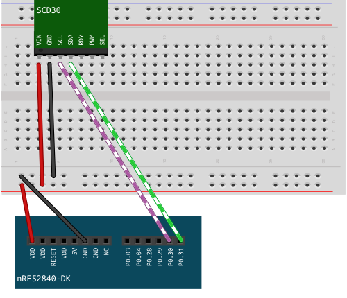
Wiring
Prerequisites
In your program, have access to the following resources:
- Timer
- P0 Pins
- 1 LED
Setting up the I2C resource
The resource we use is called twim. Twim and I2C are identical protocols, the difference is that the latter is trademarked, the former is not.
✅ Bring the following modules into scope:
#![allow(unused)]

fn main() {
// access to board peripherals:
use nrf52840_hal::{
    self as hal,
    gpio::{
        p0::{
            Parts as P0Parts
        },
        Level,
    },
    prelude::*,
    Temp,
    Timer,
    twim::{self, Twim, Error, Instance},
};
}
✅ In fn main() configure 2 pins as floating, one for the data signal (SDA) and one for the clock signal (SCL).
#![allow(unused)]
fn main() {
let scl = pins.p0_30.degrade();
let sda = pins.p0_31.degrade();
}
✅ Instantiate the pins as twim::Pins:
#![allow(unused)]
fn main() {
let pins = twim::Pins { scl, sda };
}
✅ Create a Twim instance. The method takes three arguments: TWIM peripheral, the pins and a frequency:
#![allow(unused)]
fn main() {
let i2c = Twim::new(board.TWIM0, pins, twim::Frequency::K100);
}
✅ Add a blinking loop at the end of the program. This is a way of creating a visual output, that your program is running.
#![allow(unused)]
fn main() {
loop {
        timer.delay(250_000);
        led_1.set_high().unwrap();
        timer.delay(250_000);
        led_1.set_low().unwrap();
    }
}
✅ Run the program. You should see a blinking LED.
We built the I2C instance, it needs to be connected to the sensor's interface. For this, we need the sensor's address.
✅ Find the sensor's address in the Interface Description and add it as global variable DEFAULT_ADDRESS above fn main().
Answer
```rust
pub const DEFAULT_ADDRESS: u8 = 0x61;
```
✅ Create a module scd30 for the sensor.
Inside src/scd30/mod.rs create an anonymous struct as type alias for Twim<T>.
#![allow(unused)]
fn main() {
pub struct SCD30<T: Instance>(Twim<T>);

impl<T> SCD30<T> where T: Instance {
    /// impl block
}
}
What are the <T>s?
I2C has the type Twim<T>, the T is a generic type parameter, that needs to be defined in the struct. When a generic type <T> is part of a type declaration for function arguments, it needs to be specified right after the function name. When implementing methods for that struct <T> needs to be specified and defined as well, but this happens in the opening line of the impl block.
✅ Inside the impl block, create a static method that returns an instance of the SCD30.
#![allow(unused)]
fn main() {
impl<T> SCD30<T> where T: Instance {

    pub fn init(i2c2: Twim<T>) -> Self {
        SCD30(i2c2)
    }

    /// other methods
}
}
Next, we'll create a method that can be used on a sensor instance. The purpose of the method is to write a command to the sensor that will allow us to read the sensor's firmware version number. In order to be able to do this, we need to find some information in the sensor's Interface Description:
✅ Find the I2C command for reading the firmware version.
Answer
I2C `0xD100`
✅ Find the message sequence that actually needs to be written to the sensor.
Answer
Start 0xC2 0xD1 0x00 Stop

Following the Start symbol you can find the byte that indicates that this is a *write* message: `0xC2`. This byte is one bit shift left from the sensor's address 0x61. It is already implemented in the `write()` method we will use, so we can ignore it for now.
✅ Find the message that is read from the sensor. How long is the actual information content in bytes?
Answer
The message that is read:Start 0xC3 0x03 0x42 0xF3 Stop
Notice the *read* byte. It is also just a bitshift away from the sensor's adress. After the *read* byte, are three bytes and the Stop symbol. Of the three bytes, the first is the major version number and the second is the minor version number, the last is a CRC byte. CRC is short for cyclic redundancy check which detects accidental changes in raw data. So the length of the actual information is 2 bytes.
The `read()` method returns a byte array of all bytes following the *read* byte.
✅ Calculate the Version number from the hexadecimal byte representation from the example.
Answer
|0x03|0x42|
|----|----|
|3   |66  |

So the version number in this example is 3.66.
We'll go over this method in detail, because all other methods are just variations of this theme.
✅ Add the method to the SCD30 impl block.
#![allow(unused)]
fn main() {
pub fn get_firmware_version(&mut self) -> Result<[u8; 2], Error> {
    let command:[u8; 2] = [0xd1, 0x00];
    let mut rd_buffer = [0u8; 2];

    self.0.write(DEFAULT_ADDRESS, &command)?;
    self.0.read(DEFAULT_ADDRESS, &mut rd_buffer)?;

    let major = u8::from_be(rd_buffer[0]);
    let minor = u8::from_be(rd_buffer[1]);

    Ok([major, minor])
}
}
The method takes a mutable reference to self and returns a Result type, with an Error variant and an ok variant containing an array of two unsigned 8 bit integers.
In the first line of the function body, we create an array of two u8 containing the command that is sent to the sensor. Next, we create an empty read buffer that contains two zeroed u8, because we only need the first two bytes of the bytes that are returned. We can omit the CRC byte.
Next, we call the write() method on the SCD30. It takes the address and a reference to the command as arguments. Then we call the read() method with the address and a mutable reference to the read buffer as arguments.
The last operation is converting the returned bytes into decimal numbers, and returning them as array.
✅ Go to your program file and bring the scd30 module into scope.
#![allow(unused)]
fn main() {
use knurling_session_20q4::scd30;
}
✅ In fn main()call the method on the sensor instance, and log the sensor's firmware version.
#![allow(unused)]
fn main() {
let firmware_version = sensor.get_firmware_version().unwrap();
defmt::info!("Firmware Version: {:u8}.{:u8}", firmware_version[0], firmware_version[1]);
}
Run your program. You should get a version number as log output while the LED blinks.
Congratulations! You have written the first part of a hardware driver!
Start Measuring
❗️❗️❗️ defmt update
Last week, defmt v0.1.0 to crates.io was released on crates.io. We prepared a handy guide on migrating your project from the github version of defmt to the crates.io version. New projects based on the app-template will automatically use the crates.io version from now on.
Refactoring of older instructions:
Please read the Chapter Bringing it all together and Chapter Hello Sensor and put your code into modules
After making sure, the communication is set up correctly by reading and logging the version number of the firmware, we'll start making measurements.
An example of this implementation can be found here: 11_scd_30_measure.rs.
✅ Go to section 1.4.1 of the Interface Description.
What are the message components we have to provide, so that continuous measuring is triggered?
Answer
0x00 Command byte
0x10 Command byte
0x00 Argument: Ambient Air Pressure
0x00 Argument: Ambient Air Pressure
0x81 CRC byte

The start and stop sign are automatically provided by the write method.
This Message does not only contain a command, but also an argument which allows to set a value for ambient air pressure.
The Role of Ambient Air Pressure
Together with temperature, air pressure determines how many gas molecules can be found in a defined space. The number of molecules rises when pressure increases and falls when pressure decreases. The Sensor's output unit for CO2 is ppm, parts per million, which means of one million particles (atoms or molecules) the air contains as a whole, a certain number are Carbon dioxide molecules.
If a very accurate sensor reading is necessary, the value for ambient air pressure should come from another sensor. When building an air quality monitor for work and school rooms, hardcoding a value is sufficient. The standard air pressure at sea-level is 1013.25 mbar, check you local weather station for a value if you live on higher altitudes.
For this tutorial we use the current value from Berlin, which is 1020 mbar.
Start Continuous Measurement
✅ Go to src/scd30/mod.rs. In the impl SCD30 block add a new function that takes &mut self as and pressure: u16 as arguments and returns a Result type with the variants () and Error.
Inside the function, define a mutable array for 5 u8 bytes, as this is the length of the message we will send. Leave the argument bytes and the crc byte as 0x00.
#![allow(unused)]
fn main() {
pub fn start_continuous_measurement(&mut self, pressure: u16) -> Result<(), Error> {
    let mut command: [u8; 5] = [0x00, 0x10, 0x00, 0x00, 0x00];
    // ...
    Ok(())
}
}
Next, we fill in the argument into the command. The sensor communication works in big endian byte order.
✅ Convert the u16 value into big-endian bytes. Assign the values contained in the returned slice to their respective positions in the command.
#![allow(unused)]
fn main() {
let argument_bytes = &pressure.to_be_bytes();

command[2] = argument_bytes[0];
command[3] = argument_bytes[1];
}
Calculating the CRC-Byte
If we send messages that are longer then two bytes, we need to send CRC bytes for verification after every two bytes. They need to be calculated from the argument bytes.
✅ Go to cargo.toml and add the following dependency:
#![allow(unused)]
fn main() {
crc_all = "0.2.0"
}
✅ Go back to src/scd30/mod.rs and bring the module into scope:
#![allow(unused)]
fn main() {
use crc_all::Crc;
}
✅ Check the documentation of crc_all. What arguments does the instance method Crc::<u8>::new() require?
Go to the Interface Description of the sensor, section 1.1.3 and check if you can fill in all the arguments.
Answer
|arguments|information|
|-|-|
|poly: u8|0x31|
|width: uszise|8|
|init: u8|0xff|
|xorout: u8|0x00|
|reflect: bool|false|
✅ Inside pub fn start_continuous_measurement(), instantiate a new crc byte, with your gathered information. The variable needs to be mutable. Update the crc byte with the pressure value and assign the byte to its position in the command array. Send the command to the sensor.
#![allow(unused)]
fn main() {
let mut crc = Crc::<u8>::new(0x31, 8, 0xff, 0x00, false);

crc.update(&pressure.to_be_bytes());
command[4] = crc.finish();

self.0.write(DEFAULT_ADDRESS, &command)?;
}
✅ Go to your program file. In fn main() set the ambient air pressure and start measuring!
#![allow(unused)]
fn main() {
// substitute 1020_u16 with your local value
let pressure = 1020_u16;


// ...
sensor.start_continuous_measurement(pressure).unwrap();

loop {
    ///...
}
}
✅ Run the program. you should see a blinking led.
After powering up, the sensor takes about 2 seconds until data is ready to be read. Besides just providing values, the sensor is also able to provide the information, if data is ready yet or not.
✅ In src/scd30/mod.rs, implement the data_ready method. Check the interface description for the command and length of the read buffer.
Answer
```rust
pub fn data_ready(&mut self) -> Result<bool, Error> {
let command: [u8; 2] = [0x02, 0x02];
let mut rd_buffer = [0u8; 3];

self.0.write(DEFAULT_ADDRESS, &command)?;
self.0.read(DEFAULT_ADDRESS, &mut rd_buffer)?;

Ok(u16::from_be_bytes([rd_buffer[0], rd_buffer[1]]) == 1)
}
```
✅ In your program file, before the blinking loop, open a new loop, that constantly reads the sensor if data is ready. Add a log statement that prints "Data ready." once the method returns true. Then the loop breaks.
#![allow(unused)]
fn main() {
loop {
    if sensor.data_ready().unwrap() {
        defmt::info!("Data ready.");
        break
    }
}
✅ Run your program. You should see the log output "Data ready".
Reading and Logging Sensor Data
The sensor returns three values, one for Carbon dioxide concentration, one for temperature and one for humidity. In section 1.5 in the Interface Description find the number type the sensor uses for the data.
Answer
The values the sensor returns are float numbers in big-endian format.
✅ Go to src/scd30/mod.rs. Add a new struct definition, with a field for each value.
#![allow(unused)]
fn main() {
pub struct SensorData {
    pub co2: f32,
    pub temperature: f32,
    pub humidity: f32,
}

pub const DEFAULT_ADDRESS: u8 = 0x61;
pub struct SCD30<T: Instance>(Twim<T>);

impl<T> SCD30<T>
where
    T: Instance,
{
    // ...
}
}
✅ Inside the impl SCD30 block, add a new method:
#![allow(unused)]
fn main() {
pub fn read_measurement(&mut self) -> Result<SensorData, Error> {
    // ...
    Ok(data)
}
}
- Check the Interface Description for the command and length of the read buffer.
- Make an instance of
SensorData. - Convert the relevant bytes into
f32values. Check the std documentation for conversion of big endian bytes to f32. - return the data.
Answer
#![allow(unused)]
fn main() {
pub fn read_measurement(&mut self) -> Result<SensorData, Error> {
    let command: [u8; 2] = [0x03, 0x00];
    let mut rd_buffer = [0u8; 18];

    self.0.write(DEFAULT_ADDRESS, &command)?;
    self.0.read(DEFAULT_ADDRESS, &mut rd_buffer)?;

    let data = SensorData {
        co2: f32::from_bits(u32::from_be_bytes([
            rd_buffer[0],
            rd_buffer[1],
            rd_buffer[3],
            rd_buffer[4],
        ])),
        temperature: f32::from_bits(u32::from_be_bytes([
            rd_buffer[6],
            rd_buffer[7],
            rd_buffer[9],
            rd_buffer[10],
        ])),
        humidity: f32::from_bits(u32::from_be_bytes([
            rd_buffer[12],
            rd_buffer[13],
            rd_buffer[15],
            rd_buffer[16],
        ])),
    };
    Ok(data)
}
}
✅ In your program file, inside the blinking loop, call the method and add the values and their unit to the log.
#![allow(unused)]
fn main() {
loop {
    let result = sensor.get_measurement().unwrap();

    let co2 = result.co2;
    let temp = result.temperature;
    let humidity = result.humidity;

    defmt::info!("
        CO2 {=f32} ppm
        Temperature {=f32} °C
        Humidity {=f32} %
        ", co2, temp, humidity
    );

    // blinking leds
}
}
✅ Run the program, you should see the three values in the log output.
Optional Challenges:
- The factory calibration of the sensor is pretty good, but you can still read up on how to calibrate the sensor and implement the necessary methods.
- Implement the altitude compensation method and use it instead of pressure compensation.
- Calculate absolute humidity from the relative humidity value you get from the sensor.
- Calculate the dew point.
- Implement the remaining methods listed in the sensor's Interface Description.
Red Alert!
This chapter will be refactored using Pulse Width Modulation (PWM) with the next release of the nrf-hal
The CO2 measuring device can now measure and display Carbon dioxide levels in its surroundings. In this chapter we add more interactivity: The device not only displays values, but also classifies the amount and acts accordingly: We define a normal level, a warning level, and an upper limit for carbon dioxide in the air. All levels are indicated by the LED, the upper limit will also have an acoustic warning from the buzzer.
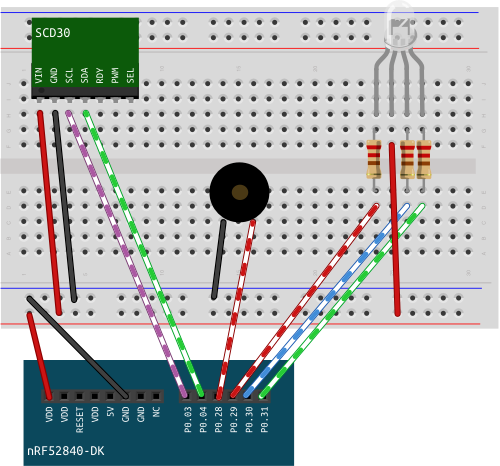
Wiring
The buzzer has two legs, one goes into ground, the other into a pin. When having several devices connected to the board, make sure they are all connected to the same ground. The pins have been changed in this diagram so that the cables don't cross. You can stick with your old pin layout.
Implementation
The Buzzer
The buzzer works in a straightforward way: It is connected to a pin and ground. Any form of voltage change lets the buzzer buzz. The lower the frequency of this change, the lower the tone of the buzz.
✅ Create a module for the buzzer. Create a type with the following methods: * init: takes a pin and puts it into push pull output mode with the initial level low. * high: puts the pin high. * low: puts the pin low. * buzz: set the pin low and and high with a break of one millisecond between each switch. Experiment with different break lengths.
✅ When initializing the sensor in fn main(), let the buzzer buzz for 500 ms, to test that it works.
CO2 Alert
For over 150 years, carbon dioxide concentration has been seen as an indicator for the quality of indoor air. Carbon dioxide levels rise with human presence in rooms and with it the concentration of other emissions of humans (microorganisms and other gasses) rise and cause a decline in air quality. Carbon dioxide is not only an easy measurable equivalent, the gas itself has significant influence on cognition and at higher levels on your health. There are different regulations regarding air quality: DIN 13779 which regulates automated ventilation considers values below 800 ppm as indicative of highest air quality, values between 800 ppm and 1000 ppm as medium quality, values between 1000 ppm and 1400 ppm as mediocre quality and values above 1400 ppm as low quality. The 150 year old Pettenkofer number which regards values above 1000 ppm as bad quality is regarded outdated for the reasoning behind it, but it's still a useful number. Current recommendations regard values below 1000 ppm as quite safe, values between 1000 ppm and 2000 ppm as noticeable and values above 2000 ppm as unhygienic. For reducing the chance of catching the corona virus, it is highly recommended to keep the value below 1000 ppm.
✅ According to what you want to achieve with the sensor, what would be your warning level and what would be your upper limit of CO2?
✅ Create a new module for CO2 alert. It contains the following:
- defines the warning level of CO2.
- defines the upper limit of CO2.
- contains a function that decides if the current CO2 level is an alert or not:
if the value is
- below warning level the LED is green.
- above warning level and below the upper limit, the LED is yellow.
- above the upper limit, the LED is red and the buzzer buzzes.
Help:
Accessing other modules in a module:
#![allow(unused)]
fn main() {
use crate::rgb_led::LEDColor;
use crate::buzzer::Buzzer;
}
User Experience
Make the following experiment: If your carbon dioxide sensor detects concentrations above 2000 ppm and you open the window, how long does it take until the concentration is back to baseline at between 400 and 500 ppm?
It probably takes longer than you expect. Leaving the buzzer on for the entire time is annoying and will not serve the purpose, as people will just turn it off completely. Having not only a visual but also an acoustic signal, when baseline is reached makes sense, as leaving the window open for an extended period of time in winter is a waste of energy. This is where we have a lot of freedom for design.
✅ Come up with your own signal scheme. What are the events that can come up? How would you like to be notified of them?
Here are some ideas:
Events:
- low humidity value (relevant in winter, with a lot of heating)
- carbon dioxide baseline (below 500 ppm)
- super high carbon dioxide level
- high humidity value (only relevant in rooms that are not heated)
- alert for temperatures, if you do not have a thermostat regulated heater but want to conserve energy.
Notifications:
- notifications don't have to be on all the time, they can serve as a reminder and go on again, if conditions do not change after a certain amount of time has passed
- LEDs can blink or have a steady light, all in different colors
- a buzzer can buzz at different frequencies or change frequencies in one signal.
- Lower frequencies are less alerting but still signaling, while higher frequencies create a sense of urgency.
Other ideas:
- a snooze button
- an indicator for data not ready/ready
✅ Implement your scheme!
Panic!
There are two types of Errors, recoverable Errors and non-recoverable ones. Non-recoverable errors are the ones that bring the system into a state where it can't operate further. This is the one where we want to focus on today.
For simulating an occurring error, we'll put an error in the code (and remove it later).
✅ Go to src/scd30/mod.rs. Change DEFAULT_ADDRESS from 0x61 to 0x62.
#![allow(unused)]
fn main() {
pub const DEFAULT_ADDRESS: u8 = 0x62;
}
This change prevents communication between the sensor and the development board.
The first time, the development board tries to communicate with the sensor is when it reads the sensor's firmware number. Let's look at this method.
#![allow(unused)]
fn main() {
pub fn get_firmware_version(&mut self) -> Result<[u8; 2], Error> {
        let command: [u8; 2] = [0xd1, 0x00];
        let mut rd_buffer = [0u8; 2];

        self.0.write(DEFAULT_ADDRESS, &command)?;
        self.0.read(DEFAULT_ADDRESS, &mut rd_buffer)?;

        let major = u8::from_be(rd_buffer[0]);
        let minor = u8::from_be(rd_buffer[1]);

        Ok([major, minor])
    }
}
The method returns the Result type. Depending on the outcome of the operation, Result contains different values: If the operation was successful, it contains a [u8; 2] array, the firmware number of the sensor. If the operation was not successful, error from the write() or the read() method is propagated and returned.
In the program we call the method and add unwrap().
#![allow(unused)]
fn main() {
let firmware_version_result = sensor.get_firmware_version().unwrap();
}
Using unwrap() returns the value in case of a success and panics the program in case of an error. This is only useful, when the occurrence of an error is not to be expected or if the error is non-recoverable anyways. Even if both of these are true for our case, handling panics manually has some benefits. Let's look at some of them.
✅ Run your program.
You should see something like this:
0.000000 ERROR panicked at 'called `Result::unwrap()` on an `Err` value: AddressNack', src/bin/13_scd_30_error_handling.rs:61:28
└─ panic_probe::print_defmt::print @ /Users/tanks/.cargo/registry/src/github.com-1ecc6299db9ec823/panic-probe-0.1.0/src/lib.rs:140
stack backtrace:
   0: HardFaultTrampoline
      <exception entry>
      <exception entry>
   1: __udf
   2: cortex_m::asm::udf
        at /Users/tanks/.cargo/registry/src/github.com-1ecc6299db9ec823/cortex-m-0.6.3/src/asm.rs:105
   3: rust_begin_unwind
        at /Users/tanks/.cargo/registry/src/github.com-1ecc6299db9ec823/panic-probe-0.1.0/src/lib.rs:75
   4: core::panicking::panic_fmt
        at /rustc/5c1f21c3b82297671ad3ae1e8c942d2ca92e84f2/src/libcore/panicking.rs:101
   5: core::option::expect_none_failed
        at /rustc/5c1f21c3b82297671ad3ae1e8c942d2ca92e84f2/src/libcore/option.rs:1272
   6: _13_scd_30_error_handling::__cortex_m_rt_main
   7: main
        at src/bin/13_scd_30_error_handling.rs:19
   8: ResetTrampoline
        at /Users/tanks/.cargo/registry/src/github.com-1ecc6299db9ec823/cortex-m-rt-0.6.13/src/lib.rs:547
   9: Reset
        at /Users/tanks/.cargo/registry/src/github.com-1ecc6299db9ec823/cortex-m-rt-0.6.13/src/lib.rs:550
The terminal process "/bin/bash '-c', 'cargo run --package knurling-session-20q4 --bin 13_scd_30_error_handling'" terminated with exit code: 134.

Terminal will be reused by tasks, press any key to close it.
In the first line, we are notified, that a panic occurred when unwrap() was called, and at what line it occurred. Reading through the rest of the message does not reveal more information, except at 7: we can see that this happened inside main().
✅ Substitute the following line
#![allow(unused)]
fn main() {
let firmware_version = sensor.get_firmware_version().unwrap();
}
with the following block of code:
#![allow(unused)]
fn main() {
let firmware_version_result = sensor.get_firmware_version();

let firmware_version = match firmware_version_result {
    Ok(version_number) => version_number,

    Err(error) => {
        panic!("Error getting firmware version: {:?}", error)
    }
};
}
Instead of calling unwrap(), we handle Result with match. In case of an error, now we get to decide what happens. We can still invoke a panic.
✅ Run the program.
You should see something like this:
0.000000 ERROR panicked at 'Error getting firmware version: AddressNack', src/bin/13_scd_30_error_handling.rs:67:13
└─ panic_probe::print_defmt::print @ /Users/tanks/.cargo/registry/src/github.com-1ecc6299db9ec823/panic-probe-0.1.0/src/lib.rs:140
stack backtrace:
   0: HardFaultTrampoline
      <exception entry>
      <exception entry>
   1: __udf
   2: cortex_m::asm::udf
        at /Users/tanks/.cargo/registry/src/github.com-1ecc6299db9ec823/cortex-m-0.6.3/src/asm.rs:105
   3: rust_begin_unwind
        at /Users/tanks/.cargo/registry/src/github.com-1ecc6299db9ec823/panic-probe-0.1.0/src/lib.rs:75
   4: core::panicking::panic_fmt
        at /rustc/5c1f21c3b82297671ad3ae1e8c942d2ca92e84f2/src/libcore/panicking.rs:101
   5: _13_scd_30_error_handling::__cortex_m_rt_main
        at src/bin/13_scd_30_error_handling.rs:67
   6: main
        at src/bin/13_scd_30_error_handling.rs:19
   7: ResetTrampoline
        at /Users/tanks/.cargo/registry/src/github.com-1ecc6299db9ec823/cortex-m-rt-0.6.13/src/lib.rs:547
   8: Reset
        at /Users/tanks/.cargo/registry/src/github.com-1ecc6299db9ec823/cortex-m-rt-0.6.13/src/lib.rs:550
The terminal process "/bin/bash '-c', 'cargo run --package knurling-session-20q4 --bin 13_scd_30_error_handling'" terminated with exit code: 134.

Terminal will be reused by tasks, press any key to close it.
By adding our part to the error message, we let a future user know what failed additionally to why the program failed, without them having to check the code lines. While the custom error message is nice, the location of the the error occurrence is not quite right, as the place of panic invocation is not the same as the occurrence of the error, and currently the quoted code line is the one where panic! was invoked. But, we can do better than that!
✅ Substitute the above shown code block with the following lines:
#![allow(unused)]
fn main() {
let firmware_version = sensor.get_firmware_version()
    .unwrap_or_else(|error| {
        panic!("Error getting firmware version: {:?}", error)
    });
}
Instead of calling unwrap() we call unwrap_or_else(). Where unwrap() panics in case of an error, unwrap_or_else() can take a closure as argument, which allows you to provide the same additional functionality as handling Result with a match statement.
✅ Run your program.
Your should see something like this:
0.000000 ERROR panicked at 'Error getting firmware version: AddressNack', src/bin/13_scd_30_error_handling.rs:63:5
└─ panic_probe::print_defmt::print @ /Users/tanks/.cargo/registry/src/github.com-1ecc6299db9ec823/panic-probe-0.1.0/src/lib.rs:140
stack backtrace:
   0: HardFaultTrampoline
      <exception entry>
      <exception entry>
   1: __udf
   2: cortex_m::asm::udf
        at /Users/tanks/.cargo/registry/src/github.com-1ecc6299db9ec823/cortex-m-0.6.3/src/asm.rs:105
   3: rust_begin_unwind
        at /Users/tanks/.cargo/registry/src/github.com-1ecc6299db9ec823/panic-probe-0.1.0/src/lib.rs:75
   4: core::panicking::panic_fmt
        at /rustc/5c1f21c3b82297671ad3ae1e8c942d2ca92e84f2/src/libcore/panicking.rs:101
   5: _13_scd_30_error_handling::__cortex_m_rt_main::{{closure}}
        at src/bin/13_scd_30_error_handling.rs:63
   6: core::result::Result<T,E>::unwrap_or_else
   7: _13_scd_30_error_handling::__cortex_m_rt_main
        at src/bin/13_scd_30_error_handling.rs:61
   8: main
        at src/bin/13_scd_30_error_handling.rs:19
   9: ResetTrampoline
        at /Users/tanks/.cargo/registry/src/github.com-1ecc6299db9ec823/cortex-m-rt-0.6.13/src/lib.rs:547
  10: Reset
        at /Users/tanks/.cargo/registry/src/github.com-1ecc6299db9ec823/cortex-m-rt-0.6.13/src/lib.rs:550
The terminal process "/bin/bash '-c', 'cargo run --package knurling-session-20q4 --bin 13_scd_30_error_handling'" terminated with exit code: 134.

Terminal will be reused by tasks, press any key to close it.
Compared to the solution of handling Result with match, we can see at least in the stack backtrace exactly where the error occurred, and not just where the panic! was invoked.
More elaborate error messages are nice, but we program on an embedded device that is supposed to be able to run without a host machine for logging. Writing your own panic handler allows you to provide "error messages" for this case, as logging messages to a host that is not there is not helpful.
✅ Go to scr/rgb_led/mod.rs. Add the following method:
#![allow(unused)]
fn main() {
pub fn error_blink_red(&mut self, timer: &mut Timer<TIMER0, OneShot>) {
    for _i in 0 ..10 {
        self.red();
        timer.delay_ms(200_u32);
        self.off();
        timer.delay_ms(200_u32);
    }
}
}
When called, the LED will blink 10 times, relatively fast in red.
✅ Call the method on the RGB LED, right before invoking panic!.
#![allow(unused)]
fn main() {
let firmware_version = sensor.get_firmware_version()
    .unwrap_or_else(|error| {
    led_indicator.error_blink_red(&mut timer);
        panic!("Error getting firmware version: {:?}", error)
    });
}
✅ Run your code.
The RGB LED will now blink red a few times before the program panics. This alerts the user that something has gone wrong, and the device needs to be rebooted, or hooked up to a host for further diagnostics.
✅ Go to src/scd30/mod.rs. Change DEFAULT_ADDRESS back to the original value: 0x61.
#![allow(unused)]
fn main() {
pub const DEFAULT_ADDRESS: u8 = 0x61;
}
e-Paper Display
Hello, e-Paper Display!
Before adding the e-Paper display to the sensor project, we'll try it out on its own. Start with a new file based on 1_hello_extended.rs.
Wiring
✅ Disconnect all jumper-wires from the development board but leave the breadboard intact.
✅ Connect the following wires of the ePaper display to the respective pins.
| Name | Color | Pin |
|---|---|---|
| vcc | red | vdd |
| gnd | black | gnd |
| din | blue | p1.01 |
| clk | yellow | p1.02 |
| cs | orange | p1.03 |
| dc | green | p1.04 |
| rst | white | p1.05 |
| busy | purple | p1.06 |
Code
Cargo.toml
✅ Add the following dependencies to the cargo.toml.
#![allow(unused)]
fn main() {
epd-waveshare = "0.4.0"
embedded-graphics = "0.6.2"
}
Instantiate SPIM
✅ Bring the spim and the p1 module into scope.
#![allow(unused)]
fn main() {
// access to board peripherals:
use nrf52840_hal::{
    self as hal,
    gpio::{p0::Parts as P0Parts, p1::Parts as P1Parts, Level},
    prelude::*,
    spim::{self, Spim},
    Timer,
};
}
✅ Configure the pins as follows:
#![allow(unused)]
fn main() {
let din = pins_1.p1_01.into_push_pull_output(Level::Low).degrade();
let clk = pins_1.p1_02.into_push_pull_output(Level::Low).degrade();
let cs = pins_1.p1_03.into_push_pull_output(Level::Low);
let dc = pins_1.p1_04.into_push_pull_output(Level::Low);
let rst = pins_1.p1_05.into_push_pull_output(Level::Low);
let busy = pins_1.p1_06.into_floating_input();
}
din is the data line, clk the clock. Both need to be floating.
cs is short for chip select, dc for data/command control pin and rst for reset. They all have to be push-pull-outputs, with initial low level.
busy is configured as input. This is the channel, where the display can communicate if it is busy or not.
The SPI protocol works similar to I2C as in that it has a clock but data to and from the peripheral device use two different channels, MISO and MOSI. We only use the MOSI line, as data is only sent to the display, and not from the display.
✅ Configure the SPIM Pins and create a new instance of the SPIM peripheral.
#![allow(unused)]
fn main() {
let spi_pins = spim::Pins {
    sck: clk,
    miso: None,
    mosi: Some(din),
};


let mut spi = Spim::new(board.SPIM3, spi_pins, spim::Frequency::K500, spim::MODE_0, 0);
}
✅ Run the program to make sure it builds. The display should not do anything at this point.
Instantiate the ePaper Display
✅ Bring the following modules into scope:
#![allow(unused)]
fn main() {
use epd_waveshare::{
    epd4in2::*,
    graphics::Display,
    prelude::*,
};
}
✅ Add an instance of the timer. ✅ Create a new instance of the 4.2 inch E Paper display. ✅ Add a default display.
#![allow(unused)]
fn main() {
// instantiate ePaper
let mut delay = Timer::new(board.TIMER1);
let mut epd4in2 = EPD4in2::new(&mut spi, cs, busy, dc, rst, &mut delay).unwrap();

let mut display = Display4in2::default();
}
✅ Run your program to make sure it builds. At this point the e-paper display switches to dark and back to light a few times.
Drawing on the ePaper Display
✅ Bring the following modules into scope:
#![allow(unused)]
fn main() {
use embedded_graphics::{
    geometry::Point,
    pixelcolor::BinaryColor,
    prelude::*,
    primitives::{ Circle, Triangle },
    style::PrimitiveStyle,
};
}
✅ The waveshare e-Paper display has a binary color system: Color is either On, or Off. On means black and Off means white.
One way to draw on the display is using primitive shapes. The crate offers circle, triangle, rectangle and line. Each one is defined by significant points and distances, the circle for example is defined by it's center and it's radius.
Each shape can be filled solid or just be depicted by a stroke around its edges. Each time content for the display is defined, it needs to be added to the display buffer, this is done with the draw method.
✅ Add the following definitions of shapes, two circles and a triangle, to your program.
#![allow(unused)]
fn main() {
let c1 = Circle::new(Point::new(171, 110), 30)
    .into_styled(PrimitiveStyle::with_fill(BinaryColor::On))
    .draw(&mut display);

let c2 = Circle::new(Point::new(229, 110), 30)
    .into_styled(PrimitiveStyle::with_fill(BinaryColor::On))
    .draw(&mut display);

let t1 = Triangle::new(Point::new(259, 120), Point::new(141, 120), Point::new(200, 200))
    .into_styled(PrimitiveStyle::with_fill(BinaryColor::On))
    .draw(&mut display);
}
Using the draw() method is not enough to actually display something on the screen. For the shapes to show up on the display, the frame needs to be updated via the spi connection, and the frame needs to be displayed.
✅ Add the following lines to your code.
#![allow(unused)]
fn main() {
epd4in2.update_frame(&mut spi, &display.buffer()).unwrap();
epd4in2.display_frame(&mut spi)
    .expect("display frame new graphics");
}
✅ Run your code. You should see a symbol constructed of two circles and a triangle.
Display Sensor Data
In this section, we're going to display the sensor data on the ePaper display. The display will show a title, "Air Quality" in a bigger font, underneath are the figures, their values and their units in a smaller font.
We're going to implement this feature, starting from 12_scd_30_alert.rs.
Wiring
✅ Reconnect the breadboard's + wire to VDD and the - wire to GND on the development board.
✅ Connect all other cables to their respective pins on the the development board.
✅ The ePaper Display needs its own power source to get enough current. Connect it to the other VDD and GND.

Instantiate SPIM
This is a repetition of last chapter. Try it on your own, and see how much you have learned! If you don't remember how, go back to the last chapter.
✅ Run your code, to make sure everything builds. Nothing new should show up on your display.
Displaying Static Text
✅ Add a new module display_helper.
✅ Inside display_helper/mod.rs bring the following resources into scope:
#![allow(unused)]
fn main() {
use epd_waveshare::{
    epd4in2::*,
};
use embedded_graphics::{
    egtext,
    fonts::{Font12x16, Font24x32, Text},
    geometry::Point,
    pixelcolor::BinaryColor,
    prelude::*,
    style::TextStyle,
    text_style,
};
}
The first step is to write the text that remains static, such as the title and the name of the figure displayed. The function takes Display4in2 the display type as mutable argument, and returns it.
Basic text with built-in fonts are added in a similar way as basic shapes. To place it on the display, you need:
- a String
- the top left coordinate of where the text starts
In our case we have the choice between 6 sizes of a simple bitmap font and color on or off for style. The font for the title is bigger than the font for the rest of the text.
✅ Add the following function to your module.
#![allow(unused)]
fn main() {
pub fn draw_text (mut display: Display4in2 ) -> Display4in2 {
    Text::new("Air Quality", Point::new(20, 30))
        .into_styled(TextStyle::new(Font24x32, BinaryColor::On))
        .draw(&mut display).unwrap();

    Text::new("Carbon Dioxide:", Point::new(20, 90))
        .into_styled(TextStyle::new(Font12x16, BinaryColor::On))
        .draw(&mut display).unwrap();

    Text::new("Temperature:", Point::new(20, 130))
        .into_styled(TextStyle::new(Font12x16, BinaryColor::On))
        .draw(&mut display).unwrap();

    Text::new("Humidity:", Point::new(20, 170))
        .into_styled(TextStyle::new(Font12x16, BinaryColor::On))
        .draw(&mut display).unwrap();

    display
}
}
✅ Go to your main file.
✅ Inside the measuring loop add an instance of the display, followed by a call to fn draw_text.
#![allow(unused)]
fn main() {
let display = Display4in2::default();

let display = display::draw_text(display);
}
✅ In order for the display to actually show what has been written to its buffer, add the following lines to update and display the frame.
#![allow(unused)]
fn main() {
epd4in2.update_frame(&mut spi, &display.buffer()).unwrap();
epd4in2.display_frame(&mut spi).expect("display frame new graphics");
}
✅ Run the your program. You should see the title followed by 3 lines of text.
Displaying Dynamic Text
While static text is rather simple, displaying values that we expect to change while the program is running using format strings is a bit more complicated because we have no dynamic memory allocation in [no_std] environments. In order to use format strings, we use the arrayvec crate that provides fixed size arrays and strings.
✅ Add the following line to the [dependencies] section of cargo.toml:
#![allow(unused)]
fn main() {
arrayvec = {version = "0.5.2", default-features = false }
}
✅ Inside display_helper/mod.rs bring the following resources into scope:
#![allow(unused)]
fn main() {
use arrayvec::ArrayString;
use core::fmt::Write;
}
✅ Add the following function to the module.
#![allow(unused)]
fn main() {
pub fn draw_numbers (value: f32, unit: &str, position: (i32, i32), mut display: Display4in2 ) -> Display4in2 {

    // content

    display

}
}
pub fn draw_numbers takes the value of the figure, its unit, the top_left coordinate of the position where the figure is to be displayed and display as arguments. The display is returned.
The next step is to create a fixed size ArrayString as write buffer buf. The buffer is needed to store the formatted dynamic data. It needs to be able to contain at least as many characters, as the we want to display.
✅ Create the write buffer and use the write! macro to write a format string that contains the value up to 2 decimal places and the unit into the write buffer buf.
#![allow(unused)]
fn main() {
let mut buf = ArrayString::<[_; 12]>::new();

write!(&mut buf, "{:.2} {}", value, unit).expect("Failed to write to buffer");
}
Next, we use the egtext! macro to write the text into the display buffer.
✅ Add the following lines to pub fn draw_numbers:
#![allow(unused)]
fn main() {
egtext!(
    text = &buf,
    top_left = position,
    style = text_style!(
        font = Font12x16,
        text_color = BinaryColor::On,
    )
)
.draw(&mut display).unwrap();
}
✅ Go to your main program file.
✅ Right before fn main() define the following constants:
#![allow(unused)]
fn main() {
const CO2_POSITION: (i32, i32) = (220, 90);
const CO2_UNIT: &str = "ppm";

const TEMP_POSITION: (i32, i32) = (220, 130);
const TEMP_UNIT: &str = "°C";

const HUMIDITY_POSITION: (i32, i32) = (220, 170);
const HUMIDITY_UNIT: &str = "%";
}
These constants set the position, where the numbers are displayed and their unit.
✅ Inside fn main, in the measuring loop but after the values are read from the sensor, call fn draw_numbers for each figure.
#![allow(unused)]
fn main() {
let display = display_helper::draw_numbers(co2, CO2_UNIT, CO2_POSITION, display);
let display = display_helper::draw_numbers(temp, TEMP_UNIT, TEMP_POSITION, display);
let display = display_helper::draw_numbers(humidity, HUMIDITY_UNIT, HUMIDITY_POSITION, display);
}
✅ Run your program. The ePaper should display the title, numbers and their units next to the static text.

The display updates very often in a very flashy way. To reduce this, we're going to change the delay at the end of the loop. The ePaper display needs about 4 seconds for each update, so measuring more often than that is pointless.
✅ Change the delay from 2000 ms to 30000ms.
#![allow(unused)]
fn main() {
timer.delay_ms(30000_u32);
led_1.set_high().unwrap();
timer.delay_ms(30000_u32);
led_1.set_low().unwrap();
}
✅ Run your program. You should see the same output, but the screen is only updated every minute.
The display still flashes when it is updated, this and other more aesthetic issues will be addressed in the last update of this project, delivered in January.
Reference Material
Project Setup
This chapter contains guides for installing tooling and setting up projects.
defmt Setup
We have created a Cargo project template to make the setup easier. Here are the setup steps.
- Install version v0.1.4 (or newer) of
probe-run, a custom Cargo runner that lets you run embedded apps if they were native apps.
$ cargo install probe-run
- Either initialize the project template with
cargo-generateor fetch a copy and initialize theCargo.tomlmanually.
$ cargo generate \
    --git https://github.com/knurling-rs/app-template \
    --branch main \
    --name my-app
If you are not using cargo-generate you'll need to manually enter the author and name fields in Cargo.toml.
 # Cargo.toml
 [package]
-# authors = ["{{authors}}"]
-# name = "{{project-name}}"
+name = "my-app"
After that there are a few TODOs in the template.
You can ripgrep for the word TODO (rg TODO .cargo .) to find them but we'll walk you through all of them in this blog post.
- Pick a chip from
probe-run --list-chipsand enter it into.cargo/config.toml.
If, for example, you have a nRF52840 Development Kit from one of our workshops then replace {{chip}} with nRF52840_xxAA.
 # .cargo/config.toml
 [target.'cfg(all(target_arch = "arm", target_os = "none"))']
-runner = "probe-run --chip {{chip}} --defmt"
+runner = "probe-run --chip nRF52840_xxAA --defmt"
- Adjust the compilation target in
.cargo/config.toml.
For the nRF52840 chip you'll want to use the thumbv7em-none-eabihf target.
 # .cargo/config.toml
 [build]
-target = "thumbv6m-none-eabi"    # Cortex-M0 and Cortex-M0+
-# target = "thumbv7m-none-eabi"    # Cortex-M3
-# target = "thumbv7em-none-eabi"   # Cortex-M4 and Cortex-M7 (no FPU)
-# target = "thumbv7em-none-eabihf" # Cortex-M4F and Cortex-M7F (with FPU)
+target = "thumbv7em-none-eabihf" # Cortex-M4F (with FPU)
If you haven't done so already, install the rust-std component for the target above:
$ rustup target add thumbv7em-none-eabihf
- Add a HAL as a dependency.
For the nRF52840 you'll want to use the nrf52840-hal.
 # Cargo.toml
 [dependencies]
-# some-hal = "1.2.3"
+nrf52840-hal = "0.11.0"
- Now that you have selected a HAL fix the HAL import in
src/lib.rs
 // my-app/src/lib.rs
-// use some_hal as _; // memory layout
+use nrf52840_hal as _; // memory layout
Hello defmt
You are now all set to cargo-run your first defmt-powered application!
There are some examples in the src/bin directory.
// my-app/src/bin/hello.rs

#![no_main]
#![no_std]

use my_app as _; // global logger + panicking-behavior + memory layout

#[cortex_m_rt::entry]
fn main() -> ! {
    defmt::info!("Hello, world!");

    my_app::exit()
}
cargo run-ning this program produces the classic "Hello, world!" output.
$ # `rb` is an alias for `run --bin`
$ cargo rb hello
    Finished dev [optimized + debuginfo] target(s) in 0.03s
flashing program ..
DONE
resetting device
0.000000 INFO Hello, world!
(..)

$ echo $?
0
Or if you are using VS code + Rust-Analyzer, instead, you can open the src/bin/hello.rs file and click the "Run" button as we demonstrated in a previous blog post.
For more details check out the defmt book.
Starting a Project from Scratch
We will show how to start an embedded project from scratch, using the nRF52840 as an example. But this guide is not limited to this development board.
Identify the microcontroller
The first step is to identify the microcontroller you'll be working with. The information about the microcontroller you'll need is:
1. Its processor architecture and sub-architecture.
This information should be in the device's data sheet or manual. In the case of the nRF52840, the processor is an ARM Cortex-M4 core. With this information you'll need to select a compatible compilation target. rustup target list will show all the supported compilation targets.
$ rustup target list
(..)
thumbv6m-none-eabi
thumbv7em-none-eabi
thumbv7em-none-eabihf
thumbv7m-none-eabi
thumbv8m.base-none-eabi
thumbv8m.main-none-eabi
thumbv8m.main-none-eabihf
The compilation targets will usually be named using the following format: $ARCHITECTURE-$VENDOR-$OS-$ABI, where the $VENDOR field is sometimes omitted. Bare metal and no_std targets, like microcontrollers, will often use none for the $OS field. When the $ABI field ends in hf it indicates that the output ELF uses the hardfloat Application Binary Interface (ABI).
The thumb targets listed above are all the currently supported ARM Cortex-M targets. The table below shows the mapping between compilation targets and ARM Cortex-M processors.
| Compilation target | Processor |
|---|---|
thumbv6m-none-eabi | ARM Cortex-M0, ARM Cortex-M0+ |
thumbv7m-none-eabi | ARM Cortex-M3 |
thumbv7em-none-eabi | ARM Cortex-M4, ARM Cortex-M7 |
thumbv7em-none-eabihf | ARM Cortex-M4F, ARM Cortex-M7F |
thumbv8m.base-none-eabi | ARM Cortex-M23 |
thumbv8m.main-none-eabi | ARM Cortex-M33, ARM Cortex-M35P |
thumbv8m.main-none-eabihf | ARM Cortex-M33F, ARM Cortex-M35PF |
The ARM Cortex-M ISA is backwards compatible so for example you could compile a program using the thumbv6m-none-eabi target and run it on an ARM Cortex-M4 microcontroller. This will work but using the thumbv7em-none-eabi results in better performance (ARMv7-M instructions will be emitted by the compiler) so it should be preferred.
❗️ You need to add the compilation target we've picked to your Rust toolchain.
$ rustup +stable target add thumbv7em-none-eabihf
2. Its memory layout.
In particular, you need to identify how much Flash and RAM memory the device has and at which address the memory is exposed. You'll find this information in the device's data sheet or reference manual.
In the case of the nRF52840, this information is in section 4.2 (Figure 2) of its Product Specification. It has:
- 1 MB of Flash that spans the address range:
0x0000_0000-0x0010_0000. - 256 KB of RAM that spans the address range:
0x2000_0000-0x2004_0000.
The knurling app-template
With all this information you'll be able to build programs for the target device.
We've created a Cargo project template called app-template is based on the cortex-m-quickstart template that lets you start a new project for the ARM Cortex-M architecture which uses all knurling tools out of the box.
🔎 for other architectures, check out other project templates by the rust-embedded organization.
❗️ Make sure you've installed probe-run and cargo-generate as advised in the installation instructions.
The recommended way to use the app-template to set up your own project is through the cargo-generate tool.
$ cargo generate \
    --git https://github.com/knurling-rs/app-template \
    --branch main \
    --name co2sensor
❗️ it may be difficult to install the cargo-generate tool on Windows due to its libgit2 (C library) dependency. Another option is to download a snapshot of the app-template from GitHub and then fill in the placeholders in Cargo.toml of the snapshot.
Once you have instantiated a project using the template you'll need to fill in the device-specific information you collected in the two previous steps.
All things that need to be changed are also marked as
TODOin the files.
- Enter your chip into
.cargo/config.toml.
 # .cargo/config.toml
 [target.'cfg(all(target_arch = "arm", target_os = "none"))']
-runner = "probe-run --chip {{chip}} --defmt"
+runner = "probe-run --chip nRF52840_xxAA --defmt"
- Adjust the compilation target in
.cargo/config.toml.
 # .cargo/config.toml
 [build]
-target = "thumbv6m-none-eabi"    # Cortex-M0 and Cortex-M0+
-# target = "thumbv7m-none-eabi"    # Cortex-M3
-# target = "thumbv7em-none-eabi"   # Cortex-M4 and Cortex-M7 (no FPU)
-# target = "thumbv7em-none-eabihf" # Cortex-M4F and Cortex-M7F (with FPU)
+target = "thumbv7em-none-eabihf" # Cortex-M4F (with FPU)
- In
Cargo.toml, Add a suitable HAL as a dependency.
 # Cargo.toml
 [dependencies]
-# some-hal = "1.2.3"
+nrf52840-hal = "0.11.0"
- Now that you have selected a HAL, fix the HAL import in
src/lib.rs
 // my-app/src/lib.rs
-// use some_hal as _; // memory layout
+use nrf52840_hal as _; // memory layout
- Check that
cargo buildworks:
$ cd co2sensor
$ cargo build
   Compiling co2sensor v0.1.0 (/Users/ferrous/co2sensor)
    Finished dev [optimized + debuginfo] target(s) in 0.65s
Congratulations! You've successfully cross compiled the sample code in co2sensor/ for your target device.
If there's no template or signs of support for a particular architecture under the rust-embedded organization then you can follow the embedonomicon to bootstrap support for the new architecture by yourself.
Flashing the program
To flash the program on the target device you'll need to identify the on-board debugger, if the development board has one. Or choose an external debugger, if the development board exposes a JTAG or SWD interface via some connector.
If the hardware debugger is supported by the probe-rs project -- for example J-Link, ST-Link or CMSIS-DAP -- then you'll be able to use probe-rs-based tools like cargo-flash and cargo-embed. This is the case of the nRF52840 DK: it has an on-board J-Link probe.
If the debugger is not supported by probe-rs then you'll need to use OpenOCD or vendor provided software to flash programs on the board.
If the board does not expose a JTAG, SWD or similar interface then the microcontroller probably comes with a bootloader as part of its stock firmware. In that case you'll need to use dfu-util or a vendor specific tool like nrfutil to flash programs onto the chip. This is the case of the nRF52840 Dongle.
Getting output
If you are using one of the probes supported by probe-rs then you can use the rtt-target library to get text output on cargo-embed. The logging functionality we used in the examples is implemented using the rtt-target crate.
If that's not the case or there's no debugger on board then you'll need to add a HAL before you can get text output from the board.
Adding a Hardware Abstraction Layer (HAL)
Now you can hopefully run programs and get output from them. To use the hardware features of the device you'll need to add a HAL to your list of dependencies. crates.io, lib.rs and awesome embedded Rust are good places to search for HALs.
After you find a HAL you'll want to get familiar with its API through its API docs and examples. HAL do not always expose the exact same API, specially when it comes to initialization and configuration of peripherals. However, most HAL will implement the embedded-hal traits. These traits allow inter-operation between the HAL and driver crates. These driver crates provide functionality to interface external devices like sensors, actuators and radios over interfaces like I2C and SPI.
If no HAL is available for your device then you'll need to build one yourself. This is usually done by first generating a Peripheral Access Crate (PAC) from a System View Description (SVD) file using the svd2rust tool. The PAC exposes a low level, but type safe, API to modify the registers on the device. Once you have a PAC you can use of the many HALs on crates.io as a reference; most of them are implemented on top of svd2rust-generated PACs.
Hello, 💡
Now that you've set up your own project from scratch, you could start playing around with it by turning on one of the DK's on-board LEDs using only the HAL. Some hints that might be helpful there:
- The Nordic Infocenter tells you which LED is connected to which pin.
blinking LEDs looking forward
Probe-run
The rust-analyzer plugin for VSCode provides you with a helpful little ▶ Run button above every test or main() function that lets you execute your code right out of the editor.
Unfortunately though, this won't work out of the box in embedded projects, since rust-analyzer will invoke cargo run when you click on ▶ Run, and cargo itself does not know how to flash and run applications on embedded targets.
However, Rust-Analyzer does seamlessly integrate with probe-run, a custom cargo runner for embedded development:
Since probe-run is a cargo runner and not a cargo subcommand, all we have to do is modify our settings to use probe-run instead whenever cargo run is called. After that, we can use the ▶ Run button like we would in a native project.
To show how to set this up, let's configure a project based on cortex-m-quickstart, namely our beginner embedded training code examples.
First, make sure you've installed Rust-Analyzer and probe-run:
$ cargo install probe-run
Then, we need to find out if our chip is supported. This also tells us which variant name to use in our configuration later.
$ probe-run --list-chips
(..)
        STM32F107VB
        STM32F107VC
nrf52 series
    Variants:
        nRF52810_xxAA
        nRF52811_xxAA
        nRF52832_xxAA
        nRF52832_xxAB
        nRF52840_xxAA
nrf51 series
(..)
Since we want to build our examples for the nRF52840 Development Kit, our variant of choice is nRF52840_xxAA.
Now, in the .cargo/config or .cargo/config.toml file of our project, we can set probe-run as the default runner to be used when running executables built for our board.
[target.thumbv7em-none-eabi]
runner = "probe-run --chip nRF52840_xxAA"
#         ^^^^^^^^^        ^^^^^^^^^^^^^

[build]
target = "thumbv7em-none-eabi" # = ARM Cortex-M4
And that's it! Now you can use the Run button as usual.
Knowledge
This chapter contains articles that explain different concepts in embedded Rust, as well as a glossary.
Articles
[std] and [no_std]?
The #![no_std] attribute in the first line of the program indicates that the program will not make use of the standard library, the std crate. Instead, it will use the core library, a subset of the standard library that does not depend on an underlying operating system (OS). It is completely platform agnostic, does not require upstream libraries, system libraries, or libc. It is necessary in environments, where this is the first code that is loaded. As a consequence, the core library does not provide all functionalities available within the std library.
Collections
The core library does not provide Vec, String, and HashMap, as they need a dynamic memory allocator (heap allocation), which core does not provide.
Without using other crates, you are restricted to types with a size known at compile time such as arrays and tuples.
Another type that works with a bit more flexibility in length are slices. A slice is a reference into a list of elements stored in contiguous memory. One way to create a slice is to take a reference to an array, a fixed-size list of elements stored in contiguous memory.
#![allow(unused)]
fn main() {
// stack allocated array
let array: [u8; 3] = [0, 1, 2];

let ref_to_array: &[u8; 3] = &array;
let slice: &[u8] = &array;
}
slice and ref_to_array are constructed in the same way but have different types. ref_to_array is represented in memory as a single pointer (1 word / 4 bytes on a 32-bit platform); slice is represented as a pointer + length (2 words / 8 bytes on a 32 bit platform).
Because slices track length at runtime rather than at compile time, they can refer to chunks of memory of any length.
#![allow(unused)]
fn main() {
let array1: [u8; 3] = [0, 1, 2];
let array2: [u8; 4] = [0, 1, 2, 3];

let mut slice: &[u8] = &array1;
log::info!("{:?}", slice); // length = 3

// now point to the other array
slice = &array2;
log::info!("{:?}", slice); // length = 4
}
Another possibility for dealing with this problem:
The heapless crate, which provides static friendly data structures that don't require dynamic memory allocation, with a fixed maximum storage size.
Further Reading:
Glossary
HAL
HAL is short for Hardware Abstraction Layer. A HAL is a set of routines that provide interfaces for programs to access hardware resources.
GPIO
GPIO is short for General Purpose Input Output. GPIOs are programmable, digital or sometimes analogue signal pins that can be used as interfaces to other systems or devices.
Pin Configurations
Floating
A floating pin is neither connected VCC nor ground. The voltage will match the residual voltage.
Push-Pull-Output
A pin that is configured as push–pull output can switch between high and low voltage.
Open-Drain-Output
Open Drain outputs switch between "disconnected" and "connected to ground".
Pull-Up-Input
A pin that is configured as pull-up input is set to VCC, as long as it is not overwritten by an external source. This setting prevents the pin from floating, which can cause noise in the system.
Protocols
I2C
The I2C protocol has two signal lines, one for data (SDA) and one for the clock signal (SCL). An I2C transaction consists of one or more messages. Each message begins with a start symbol. A message is either write or read, indicated by the next bit in the row. Following this comes the actual message in form of bytes. The message ends with a stop symbol. The clock signal rises and falls in a specified frequency.
Many devices can be connected to the same I2C bus and messages can be send to a particular device by specifying its I2C address.
Troubleshooting
Migrating from git defmt to stable defmt
People that started working on this book before 2020-11-11 are using the unstable git version of the defmt logging framework.
On 2020-11-11, a stable version of defmt became available on crates.io.
If you are still using the git version you are encouraged to migrate to the crates.io version!
Here's how:
- In your
app-templateproject, change the rootCargo.tomlas shown below:
 [workspace]
 members = ["testsuite"]

-[dependencies.defmt]
-git = "https://github.com/knurling-rs/defmt"
-branch = "main"
-
-[dependencies.defmt-rtt]
-git = "https://github.com/knurling-rs/defmt"
-branch = "main"
-
-[dependencies.panic-probe]
-git = "https://github.com/knurling-rs/probe-run"
-branch = "main"
-
 [dependencies]
+defmt = "0.1.0"
+defmt-rtt = "0.1.0"
+panic-probe = { version = "0.1.0", features = ["print-defmt"] }
 cortex-m = "0.6.4"
 cortex-m-rt = "0.6.13"
- In your
app-templateproject, also change thetestsuite/Cargo.tomlas shown below:
 name = "test"
 harness = false

-[dependencies.defmt]
-git = "https://github.com/knurling-rs/defmt"
-branch = "main"
-
-[dependencies.defmt-rtt]
-git = "https://github.com/knurling-rs/defmt"
-branch = "main"
-
-[dependencies.panic-probe]
-git = "https://github.com/knurling-rs/probe-run"
-branch = "main"
-# enable the `print-defmt` feature for more complete test output
-features = ["print-defmt"]
-
 [dependencies]
+defmt = "0.1.0"
+defmt-rtt = "0.1.0"
+panic-probe = { version = "0.1.0", features = ["print-defmt"] }
 cortex-m = "0.6.3"
 cortex-m-rt = "0.6.12"
- Finally, install
probe-runversion v0.1.4 (or newer)
$ cargo install probe-run -f
Now you can resume working on your project!